Trimming potentiometers are essential components in various electronic circuits, allowing for precise adjustment of resistance values. The 3329 Trimming Potentiometer is a popular choice among engineers and hobbyists due to its reliability and accuracy. As a supplier of the 3329 Trimming Potentiometer, I understand the importance of ensuring its functionality before integrating it into a circuit. In this blog post, I will guide you through the process of testing the functionality of a 3329 Trimming Potentiometer.
Understanding the 3329 Trimming Potentiometer
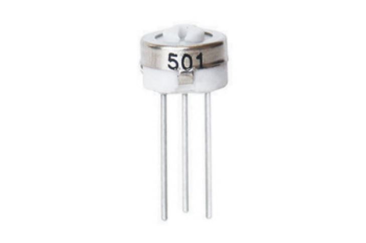
Before diving into the testing process, it's crucial to have a basic understanding of what a 3329 Trimming Potentiometer is and how it works. A trimming potentiometer, also known as a trim pot, is a variable resistor that can be adjusted to fine - tune the resistance in a circuit. The 3329 Trimming Potentiometer is a single - turn device, which means it can be adjusted through a single rotation of its shaft.
It typically has three terminals: two outer terminals and one wiper terminal. The resistance between the two outer terminals is the total resistance of the potentiometer, often referred to as its nominal resistance. The wiper terminal can be moved along the resistive element, changing the resistance between the wiper and either of the outer terminals.
Tools Required for Testing
To test the functionality of a 3329 Trimming Potentiometer, you will need the following tools:

- Multimeter: A multimeter is an essential tool for measuring electrical properties such as resistance, voltage, and current. Make sure your multimeter has a resistance measurement function.
- Screwdriver: Since the 3329 Trimming Potentiometer is adjusted using a small screw, you will need an appropriate screwdriver to turn the shaft.
Step - by - Step Testing Process
Step 1: Safety First
Before starting the testing process, ensure that the circuit in which the potentiometer is to be used is powered off. This will prevent any electrical shocks and protect both you and the components from damage.
Step 2: Visual Inspection
Examine the 3329 Trimming Potentiometer visually. Look for any signs of physical damage such as cracks, bent pins, or corrosion. A damaged potentiometer may not function correctly and should be replaced.
Step 3: Set Up the Multimeter
Turn on your multimeter and set it to the resistance measurement mode. Select an appropriate range based on the nominal resistance of the 3329 Trimming Potentiometer. For example, if the nominal resistance is 10 kΩ, you can set the multimeter to a range that includes 10 kΩ, such as 20 kΩ.
Step 4: Measure the Total Resistance
Connect the two probes of the multimeter to the two outer terminals of the 3329 Trimming Potentiometer. The multimeter should display a resistance value close to the nominal resistance specified by the manufacturer. For example, if the potentiometer is labeled as a 10 kΩ trim pot, the measured resistance should be around 10 kΩ, with some tolerance. The tolerance is usually specified on the potentiometer or in its datasheet. If the measured resistance is significantly different from the nominal value, the potentiometer may be defective.
Step 5: Check the Wiper Resistance
Keep one probe of the multimeter connected to one of the outer terminals and connect the other probe to the wiper terminal. Slowly turn the shaft of the potentiometer using the screwdriver. As you turn the shaft, the resistance value displayed on the multimeter should change smoothly. If the resistance value jumps erratically or does not change at all, there may be a problem with the wiper or the resistive element.
Step 6: Reverse the Probes
Repeat Step 5, but this time connect the probe that was previously connected to the outer terminal to the other outer terminal. Again, turn the shaft of the potentiometer and observe the change in resistance. The resistance should change smoothly in the opposite direction compared to the previous test.
Comparing with Other Trimming Potentiometers
If you are familiar with other trimming potentiometers like the 3362 Trimming Potentiometer or the 3386 Trimming Potentiometer, you can compare the behavior of the 3329 Trimming Potentiometer with them. The basic testing principles are similar, but each potentiometer may have different characteristics such as different nominal resistances, tolerances, and linearity.
Troubleshooting
If the 3329 Trimming Potentiometer fails the tests, here are some possible causes and solutions:
- Physical Damage: As mentioned earlier, physical damage can cause the potentiometer to malfunction. If you notice any visible damage, replace the potentiometer.
- Dirty or Worn - Out Resistive Element: Over time, the resistive element inside the potentiometer may become dirty or worn out. You can try cleaning the potentiometer using a contact cleaner, but in most cases, a worn - out resistive element will require replacement.
- Loose Connections: Check the connections between the potentiometer and the multimeter probes. Make sure they are secure. Loose connections can lead to inaccurate resistance measurements.
Importance of Testing
Testing the functionality of a 3329 Trimming Potentiometer before using it in a circuit is crucial for several reasons. Firstly, it ensures that the potentiometer will perform as expected, which is essential for the proper functioning of the entire circuit. Secondly, it helps to identify any defective components early on, saving time and resources that would otherwise be spent on troubleshooting a faulty circuit.
Conclusion
In conclusion, testing the functionality of a 3329 Trimming Potentiometer is a straightforward process that can be done using a multimeter and a screwdriver. By following the steps outlined in this blog post, you can ensure that the potentiometer is in good working condition before integrating it into your electronic circuit.
If you are in the market for high - quality 3329 Trimming Potentiometers or other related products, we are here to assist you. We offer a wide range of trimming potentiometers, including the 3329 Trimming Potentiometer, to meet your specific needs. Contact us to discuss your requirements and start a procurement negotiation.
References
- Electronic Component Datasheets
- Basic Electrical Engineering Textbooks


