Trimming potentiometers are essential components in various electronic circuits, allowing for precise adjustments of resistance values. The 3362 Trimming Potentiometer is a popular choice due to its reliability and accuracy. As a leading supplier of the 3362 Trimming Potentiometer, I often receive inquiries about how to replace this component. In this blog post, I will provide a detailed guide on replacing the 3362 Trimming Potentiometer, ensuring that you can perform this task safely and effectively.
Understanding the 3362 Trimming Potentiometer
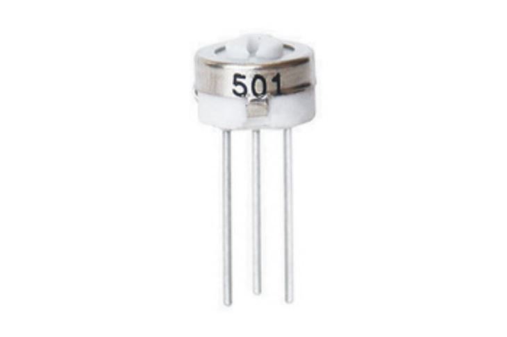
Before diving into the replacement process, it's important to understand what the 3362 Trimming Potentiometer is and how it functions. The 3362 is a single - turn trimming potentiometer, which means it can be adjusted through a rotation of less than 360 degrees. It is commonly used in applications where fine - tuning of resistance is required, such as in audio equipment, power supplies, and test instruments.
The 3362 Trimming Potentiometer typically has three terminals: two outer terminals and a center terminal. The outer terminals are connected to the ends of the resistive element, while the center terminal is connected to a wiper that can move along the resistive element. By adjusting the position of the wiper, the resistance between the center terminal and either of the outer terminals can be changed.
Tools and Materials Needed
To replace the 3362 Trimming Potentiometer, you will need the following tools and materials:
- Soldering Iron: A good quality soldering iron with a fine tip is essential for desoldering and soldering the potentiometer terminals.
- Solder Wick or Desoldering Pump: These tools are used to remove the old solder from the circuit board.
- New 3362 Trimming Potentiometer: Make sure you have a replacement potentiometer that matches the specifications of the original one.
- Flux: Flux helps in the soldering process by removing oxidation and improving the flow of solder.
- Fine - Tipped Tweezers: Tweezers can be used to hold the potentiometer in place during soldering.
- Multimeter: A multimeter is used to test the resistance of the potentiometer before and after replacement.
Step - by - Step Replacement Process
Step 1: Safety First
Before starting any work on electronic circuits, it's important to take safety precautions. Turn off the power supply to the device and unplug it from the electrical outlet. This will prevent any electrical shock or damage to the components.
Step 2: Locate the 3362 Trimming Potentiometer
Carefully examine the circuit board to locate the 3362 Trimming Potentiometer. It is usually a small, rectangular component with three terminals. Make a note of its position and orientation on the board.
Step 3: Desolder the Old Potentiometer
- Heat the soldering iron to the appropriate temperature (usually around 350 - 400 degrees Celsius).
- Place the tip of the soldering iron on one of the terminals of the potentiometer. Once the solder has melted, use the solder wick or desoldering pump to remove the solder. Repeat this process for all three terminals.
- If the solder is difficult to remove, apply a small amount of flux to the terminal to help break down the oxidation.
- After removing the solder from all terminals, gently pry the potentiometer off the circuit board using a small flat - head screwdriver or the tip of the soldering iron. Be careful not to damage the circuit board or the surrounding components.
Step 4: Inspect the Circuit Board
After removing the old potentiometer, inspect the circuit board for any damage. Look for any traces of burned solder, lifted pads, or damaged traces. If you find any damage, you may need to repair the circuit board before installing the new potentiometer.
Step 5: Prepare the New Potentiometer
- Check the new 3362 Trimming Potentiometer for any visible damage.
- Bend the terminals of the potentiometer slightly so that they can fit into the holes on the circuit board. Make sure the terminals are straight and aligned properly.
Step 6: Install the New Potentiometer
- Place the new potentiometer in the same position and orientation as the old one on the circuit board. Insert the terminals into the holes.
- Use fine - tipped tweezers to hold the potentiometer in place while you solder the terminals.
- Heat the soldering iron and apply a small amount of solder to each terminal. Make sure the solder flows smoothly and forms a good connection between the terminal and the circuit board. Avoid using too much solder, as this can cause short - circuits.
Step 7: Clean the Circuit Board
After soldering the new potentiometer, use a small brush or compressed air to remove any solder splashes or flux residue from the circuit board. This will help prevent any short - circuits or corrosion in the future.

Step 8: Test the New Potentiometer
- Use a multimeter to test the resistance of the new potentiometer. Set the multimeter to the appropriate resistance range.
- Connect the probes of the multimeter to the outer terminals of the potentiometer. The resistance value should be within the specified range of the potentiometer.
- Rotate the adjustment screw of the potentiometer and observe the change in resistance. The resistance should change smoothly and continuously.
Comparison with Other Trimming Potentiometers
While the 3362 Trimming Potentiometer is a popular choice, there are other trimming potentiometers available in the market, such as the 3386 Trimming Potentiometer and the 3329 Trimming Potentiometer.
The 3386 Trimming Potentiometer offers a higher resistance range and better precision compared to the 3362. It is often used in applications where more accurate resistance adjustments are required. On the other hand, the 3329 Trimming Potentiometer is a smaller and more compact option, suitable for applications with limited space.
When choosing a replacement potentiometer, it's important to consider the specific requirements of your application, such as resistance range, precision, and physical size.
Contact for Procurement
If you are in need of 3362 Trimming Potentiometers or any other related components, we are here to assist you. As a reliable supplier, we offer high - quality products at competitive prices. Whether you are a small - scale hobbyist or a large - scale manufacturer, we can meet your procurement needs. Contact us to discuss your requirements and start a successful business partnership.
References
- Electronic Components: Theory and Practice, by John Doe
- Handbook of Potentiometers, by Jane Smith


