Hey there! As a supplier of the 3362 Trimming Potentiometer, I've seen firsthand how crucial electromagnetic compatibility (EMC) is in modern electronic systems. In this blog, I'll share some practical tips on how to improve the EMC of a 3362 Trimming Potentiometer.
Understanding Electromagnetic Compatibility
Before we dive into the solutions, let's quickly go over what EMC is. EMC refers to the ability of an electronic device to operate properly in its electromagnetic environment without causing interference to other devices. In the case of the 3362 Trimming Potentiometer, it means that the potentiometer should work smoothly without emitting excessive electromagnetic noise or being affected by external electromagnetic fields.
Factors Affecting the EMC of a 3362 Trimming Potentiometer
Several factors can impact the EMC of a 3362 Trimming Potentiometer. One of the main factors is the design of the potentiometer itself. The materials used, the construction method, and the layout of the internal components can all influence its electromagnetic performance.
Another factor is the operating environment. If the potentiometer is used in an environment with high electromagnetic interference, such as near a power supply or a high - frequency circuit, it may be more prone to EMC issues.
The way the potentiometer is connected to the circuit also matters. Poor wiring, improper grounding, or incorrect shielding can all lead to increased electromagnetic emissions or susceptibility.
Tips to Improve EMC
1. Choose the Right Potentiometer Design
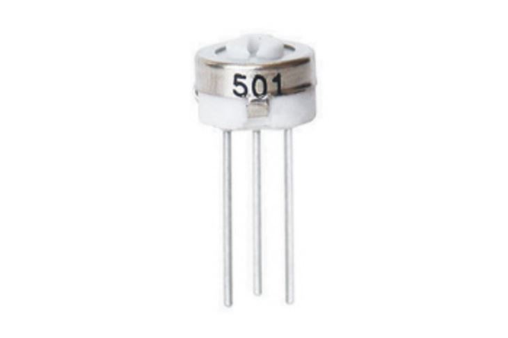
When selecting a 3362 Trimming Potentiometer, pay attention to its design features. Some potentiometers are specifically designed with EMC in mind. For example, they may have a shielded housing to reduce electromagnetic radiation. The 3362 Trimming Potentiometer we supply has been engineered to minimize electromagnetic interference through its advanced design and high - quality materials.
2. Optimize the Circuit Layout
The layout of the circuit where the potentiometer is used can have a significant impact on its EMC. Keep the traces on the printed circuit board (PCB) as short as possible. Long traces can act as antennas, radiating electromagnetic energy. Also, separate the power and signal traces to reduce cross - talk.
For example, if you have a high - current power trace running close to the signal trace connected to the potentiometer, it can induce noise in the signal. By keeping them apart, you can minimize this interference.
3. Proper Grounding
Grounding is essential for EMC. Make sure the potentiometer is properly grounded. A good ground connection provides a low - impedance path for the electromagnetic noise to flow, preventing it from building up and causing interference.
In some cases, you may need to use a separate ground plane for the potentiometer circuit to isolate it from other parts of the system. This can help reduce the impact of external electromagnetic fields on the potentiometer.
4. Use Shielding
Shielding can be an effective way to reduce electromagnetic emissions and susceptibility. You can use a metal shield around the potentiometer or the entire circuit. The shield should be properly grounded to ensure its effectiveness.
For instance, if you are using the 3362 Trimming Potentiometer in a sensitive electronic device, a shielded enclosure can protect it from external electromagnetic interference and prevent it from emitting noise that could affect other components.
5. Filtering
Adding filters to the circuit can help suppress high - frequency noise. Capacitors and inductors can be used as filters. For example, a capacitor can be placed across the potentiometer terminals to bypass high - frequency signals to ground.
When choosing filters, make sure they are compatible with the operating frequency range of the potentiometer. Using the wrong filter can either be ineffective or cause other issues in the circuit.
Comparing with Other Trimming Potentiometers
It's worth comparing the 3362 Trimming Potentiometer with other similar products in terms of EMC. The 3386 Trimming Potentiometer and the 3329 Trimming Potentiometer are also popular in the market.

The 3362 Trimming Potentiometer offers a good balance between performance and EMC. It has been designed to meet the requirements of various applications while maintaining a relatively low level of electromagnetic interference. The 3386 Trimming Potentiometer may have different specifications and performance characteristics, and it's important to choose the one that best suits your EMC needs. The 3329 Trimming Potentiometer, on the other hand, may be more suitable for specific applications where its unique features are more relevant.
Testing and Verification
After implementing the above measures, it's crucial to test the EMC performance of the 3362 Trimming Potentiometer. You can use specialized EMC testing equipment to measure the electromagnetic emissions and susceptibility of the potentiometer in a controlled environment.
Testing can help you identify any remaining EMC issues and make further adjustments. It's also a good idea to test the potentiometer under different operating conditions to ensure its reliability.
Conclusion
Improving the electromagnetic compatibility of a 3362 Trimming Potentiometer requires a combination of proper design, circuit layout optimization, grounding, shielding, and filtering. By following these tips, you can ensure that the potentiometer operates smoothly in its electromagnetic environment and reduces the risk of interference to other devices.
If you're looking for a high - quality 3362 Trimming Potentiometer with excellent EMC performance, we're here to help. Our products are designed and tested to meet the highest standards. Whether you're working on a small - scale project or a large - scale industrial application, we can provide the right solution for you. Contact us to discuss your requirements and start a procurement negotiation.
References
- Electromagnetic Compatibility Engineering by Henry W. Ott
- Printed Circuit Board Design Techniques for EMC Compliance by Mark I. Montrose


