As a trusted supplier of the 3329 Trimming Potentiometer, I understand the importance of proper calibration for optimal performance. In this blog post, I'll guide you through the process of calibrating the 3329 Trimming Potentiometer, sharing insights and tips based on my experience in the field.
Understanding the 3329 Trimming Potentiometer
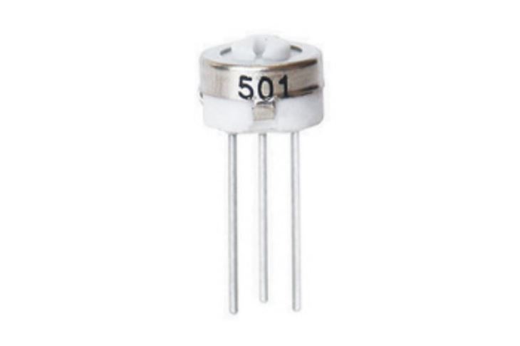
Before we dive into the calibration process, let's briefly understand what the 3329 Trimming Potentiometer is. The 3329 Trimming Potentiometer is a single - turn potentiometer commonly used in various electronic circuits. It allows for fine - tuning of electrical resistance, which is crucial for adjusting voltage levels, signal strength, and other electrical parameters in a circuit.
Tools Required for Calibration
To calibrate the 3329 Trimming Potentiometer, you'll need the following tools:
- Multimeter: This is essential for measuring the resistance across the potentiometer. A digital multimeter is preferred for its accuracy.
- Screwdriver: A small, precision screwdriver that fits the adjustment slot of the 3329 Trimming Potentiometer.
- Power Supply: If the calibration is to be done in a live circuit, a stable power supply is required.
Pre - calibration Checks
Before you start the calibration process, it's important to perform some pre - calibration checks:
- Visual Inspection: Examine the potentiometer for any physical damage, such as a broken shaft or damaged leads. If there is any visible damage, the potentiometer may need to be replaced.
- Circuit Check: Ensure that the circuit in which the potentiometer is installed is properly functioning. A faulty circuit can lead to inaccurate calibration results.
- Multimeter Setup: Set your multimeter to the appropriate resistance range. For the 3329 Trimming Potentiometer, a range that can measure up to the maximum rated resistance of the potentiometer is usually sufficient.
Calibration Steps
- Isolate the Potentiometer (if necessary): If the calibration can be done without power, it's advisable to isolate the potentiometer from the circuit. This can be done by disconnecting the power supply and removing any components that may affect the resistance measurement.
- Initial Resistance Measurement: Use the multimeter to measure the initial resistance across the two outer terminals of the 3329 Trimming Potentiometer. This will give you a baseline reading.
- Adjustment: Insert the screwdriver into the adjustment slot of the potentiometer. Turn the screwdriver slowly in either direction. As you turn the screwdriver, the resistance measured by the multimeter will change.
- Target Resistance Setting: Determine the target resistance value based on your circuit requirements. This value can be specified in the circuit design or determined through testing. Slowly adjust the potentiometer until the multimeter reads the target resistance value.
- Stability Check: Once you've reached the target resistance value, hold the screwdriver in place and check the stability of the resistance reading. The reading should remain relatively constant. If it fluctuates, there may be a problem with the potentiometer or the circuit.
- Final Check in the Circuit: If the calibration was done with the potentiometer isolated, reconnect it to the circuit and power on the circuit. Check the electrical parameters of the circuit, such as voltage and signal strength, to ensure that they are within the desired range.
Troubleshooting Common Issues
- Resistance Not Changing: If the resistance does not change when you turn the adjustment screw, the potentiometer may be faulty. Check for any loose connections or internal damage.
- Inconsistent Resistance Readings: Inconsistent readings can be caused by a dirty or worn - out potentiometer. Try cleaning the potentiometer contacts with a contact cleaner.
- Difficulty in Reaching the Target Resistance: If you're having trouble reaching the target resistance value, double - check the circuit design and the target value. There may be other components in the circuit affecting the resistance.
Comparison with Other Trimming Potentiometers
The 3329 Trimming Potentiometer is just one of many trimming potentiometers available in the market. For example, the 3362 Trimming Potentiometer and the 3386 Trimming Potentiometer also have their own unique features. The 3362 is known for its high - precision and wide resistance range, while the 3386 offers a larger size and higher power handling capacity. When choosing a trimming potentiometer, consider the specific requirements of your circuit, such as accuracy, power rating, and physical size.
Importance of Proper Calibration
Proper calibration of the 3329 Trimming Potentiometer is crucial for the overall performance of the circuit. Incorrect calibration can lead to inaccurate voltage levels, signal distortion, and even circuit failure. By following the calibration process outlined above, you can ensure that your potentiometer is operating at its best and that your circuit is functioning as intended.

Conclusion
Calibrating the 3329 Trimming Potentiometer is a relatively straightforward process that can significantly improve the performance of your electronic circuits. By using the right tools, following the proper calibration steps, and troubleshooting any issues that arise, you can ensure that your 3329 Trimming Potentiometer is calibrated accurately.
If you're in the market for high - quality 3329 Trimming Potentiometers or need further assistance with calibration or circuit design, feel free to reach out to us. We're here to provide you with the best products and support for your electronic needs.
References
- Electronic Circuit Design Handbook
- Potentiometer Manufacturer's Documentation


