A bridge circuit is a fundamental electrical circuit used for measuring unknown electrical quantities, such as resistance, inductance, or capacitance. Balancing a bridge circuit is crucial for accurate measurements, and one effective way to achieve this balance is by using a trimming potentiometer. In this blog post, I'll share insights on how to adjust the 3386 Trimming Potentiometer to balance a bridge circuit, drawing on my experience as a supplier of these high - quality components.

Understanding the Bridge Circuit
Before delving into the adjustment process, it's essential to have a basic understanding of a bridge circuit. The most common type is the Wheatstone bridge, which consists of four resistive arms arranged in a diamond - shaped configuration. A voltage source is connected across one diagonal, and a detector (such as a galvanometer) is connected across the other diagonal. When the bridge is balanced, the potential difference across the detector is zero, indicating that the ratio of resistances in the two pairs of arms is equal.
The general formula for a balanced Wheatstone bridge is (R_1/R_2 = R_3/R_4), where (R_1), (R_2), (R_3), and (R_4) are the resistances of the four arms of the bridge. Any deviation from this ratio will result in a non - zero potential across the detector, and this is where the trimming potentiometer comes in handy.
The Role of the 3386 Trimming Potentiometer
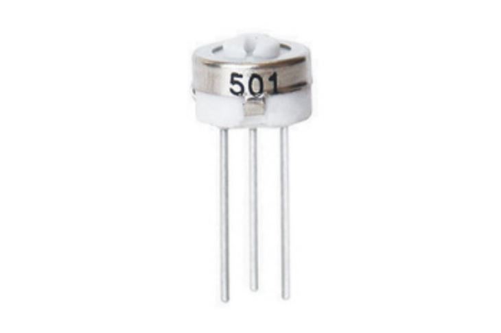
The 3386 Trimming Potentiometer is a single - turn, precision device that allows for fine adjustments of resistance. It can be incorporated into one of the arms of the bridge circuit to fine - tune the balance. The potentiometer has three terminals: two outer terminals that are connected across the entire resistance element and a center terminal that can be adjusted to vary the resistance between it and one of the outer terminals.
Preparation for Adjustment
Before attempting to adjust the 3386 Trimming Potentiometer, you need to ensure that the bridge circuit is properly set up. First, connect all the resistive elements and the voltage source correctly according to the circuit diagram. Make sure that the detector is functioning properly and is sensitive enough to detect small potential differences.
You will also need a suitable tool for adjusting the potentiometer. Most 3386 Trimming Potentiometers can be adjusted using a small screwdriver or a specialized adjustment tool. It's important to handle the potentiometer gently to avoid damaging the delicate internal components.
Step - by - Step Adjustment Process
- Initial Setup:
- Start by setting the 3386 Trimming Potentiometer to its approximate mid - position. This provides a good starting point for the adjustment process.
- Power on the bridge circuit and observe the reading on the detector. If the reading is far from zero, it indicates a significant imbalance in the bridge.
- Coarse Adjustment:
- Begin making coarse adjustments to the potentiometer. Turn the adjustment screw in one direction and observe the change in the detector reading. If the reading moves towards zero, continue turning in the same direction. If it moves further away from zero, reverse the direction of turning.
- Keep making these coarse adjustments until the detector reading is relatively close to zero. At this point, you have achieved a rough balance in the bridge circuit.
- Fine Adjustment:
- Once the coarse adjustment has brought the detector reading close to zero, it's time for fine adjustment. Make very small turns of the adjustment screw, typically in increments of a fraction of a turn.
- Observe the detector reading carefully after each small adjustment. The goal is to get the detector reading as close to zero as possible. For highly sensitive applications, you may need to make extremely fine adjustments to achieve the desired level of balance.
- Verification:
- After making the fine adjustments, leave the bridge circuit running for a few minutes to ensure that the balance is stable. Sometimes, electrical components can heat up or experience small changes in resistance over time, which may affect the balance.
- If the detector reading remains close to zero during this verification period, then the bridge circuit is successfully balanced using the 3386 Trimming Potentiometer.
Troubleshooting
If you encounter difficulties in balancing the bridge circuit, there are several potential issues to consider:
- Component Faults: Check all the resistive elements in the bridge circuit for any signs of damage or incorrect values. A faulty resistor can prevent the bridge from being balanced.
- Potentiometer Issues: Ensure that the 3386 Trimming Potentiometer is functioning correctly. Check for loose connections or internal damage. If the potentiometer is not adjusting smoothly, it may need to be replaced.
- Electrical Noise: Electrical noise in the circuit can interfere with the detector reading. Try using shielded cables or adding filtering components to reduce the noise.
Comparison with Other Trimming Potentiometers
While the 3386 Trimming Potentiometer is a popular choice for balancing bridge circuits, there are other options available as well. For example, the 3329 Trimming Potentiometer and the 3362 Trimming Potentiometer are also widely used.
The 3329 Trimming Potentiometer is known for its compact size, making it suitable for applications where space is limited. However, it may have a slightly lower precision compared to the 3386. The 3362 Trimming Potentiometer offers a higher power rating and is more suitable for applications that require handling larger currents.
When choosing a trimming potentiometer for your bridge circuit, consider factors such as precision, size, power rating, and cost. The 3386 Trimming Potentiometer strikes a good balance between precision and general - purpose usability, making it a popular choice for many bridge - circuit applications.
Conclusion
Balancing a bridge circuit using the 3386 Trimming Potentiometer is a skill that requires patience and careful adjustment. By following the steps outlined in this blog post, you can achieve accurate balance in your bridge circuit, which is essential for precise electrical measurements.
As a supplier of the 3386 Trimming Potentiometer, I understand the importance of providing high - quality components for your electrical projects. If you are in need of 3386 Trimming Potentiometers or have any questions about their application in bridge circuits, I encourage you to reach out for a procurement discussion. We are committed to providing you with the best products and support for your specific needs.
References
- Horowitz, P., & Hill, W. (1989). The Art of Electronics. Cambridge University Press.
- Boylestad, R. L., & Nashelsky, L. (2010). Electronic Devices and Circuit Theory. Pearson.


