Hey there! I'm a supplier of the 3386 Trimming Potentiometer, and today I'm gonna walk you through how to use this nifty little device in a feedback control loop.
First off, let's get a basic understanding of what a 3386 Trimming Potentiometer is. It's a single - turn potentiometer that gives you a way to adjust resistance within a circuit. You can find more details about it on our website 3386 Trimming Potentiometer. It's a really handy component, especially when you need to fine - tune the performance of a circuit.
What's a Feedback Control Loop?
A feedback control loop is a system where the output of a process is measured and then fed back into the system to adjust the input. It's like a self - correcting mechanism. For example, think of a thermostat in your home. It measures the temperature (output) and then adjusts the heating or cooling system (input) to keep the temperature at a set level.
In an electrical circuit, a feedback control loop can be used to regulate voltage, current, or other electrical parameters. And that's where our 3386 Trimming Potentiometer comes in.
Why Use a 3386 Trimming Potentiometer in a Feedback Control Loop?
The 3386 Trimming Potentiometer allows you to make precise adjustments to the resistance in the circuit. This adjustment can be used to change the gain, offset, or other characteristics of the feedback loop. For instance, if you're using an amplifier in a feedback loop, the potentiometer can be used to adjust the gain of the amplifier, ensuring that the output signal is at the desired level.
Setting Up the 3386 Trimming Potentiometer in a Feedback Control Loop
1. Circuit Design
Before you start using the 3386 Trimming Potentiometer, you need to have a clear circuit design. First, identify the part of the feedback loop where you want to make the adjustment. Usually, this is a point where changing the resistance will have a direct impact on the parameter you're trying to control.
Let's say you're building a voltage regulator circuit. The feedback loop in this circuit measures the output voltage and compares it to a reference voltage. The difference between these two voltages is used to adjust the input to the regulator. You can place the 3386 Trimming Potentiometer in the feedback path to adjust the gain of the error amplifier.
2. Mounting the Potentiometer
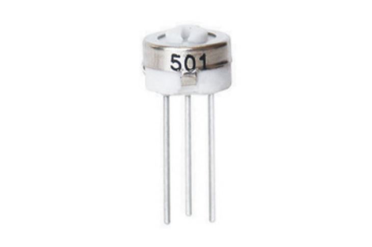
Once you have the circuit design, it's time to mount the 3386 Trimming Potentiometer on the circuit board. Make sure to follow the proper soldering techniques to ensure a good electrical connection. The potentiometer has three terminals: two outer terminals and a center terminal. The outer terminals are connected to the ends of the resistive element, and the center terminal is connected to the wiper, which can be adjusted to change the resistance.
3. Initial Adjustment
After mounting the potentiometer, you need to make an initial adjustment. Start by setting the potentiometer to its mid - position. This is a good starting point because it gives you room to increase or decrease the resistance as needed.
4. Testing and Fine - Tuning
Now it's time to test the circuit. Apply power to the circuit and measure the output parameter. If the output is not at the desired level, use a small screwdriver to adjust the potentiometer. Turn the screwdriver slowly and observe how the output changes. Keep adjusting until you get the desired output.

Comparison with Other Trimming Potentiometers
We also offer other trimming potentiometers like the 3329 Trimming Potentiometer and the 3362 Trimming Potentiometer. The 3329 is a smaller potentiometer, which is great for applications where space is limited. The 3362 has a different resistance range and tolerance compared to the 3386.
The 3386 Trimming Potentiometer stands out because of its high precision and wide resistance range. It's suitable for applications where you need a more accurate adjustment, such as in high - end audio equipment or precision measurement circuits.
Troubleshooting
Sometimes, you might run into issues when using the 3386 Trimming Potentiometer in a feedback control loop. Here are some common problems and how to fix them:
1. No Output Change
If you're adjusting the potentiometer and there's no change in the output, check the electrical connections. Make sure that the potentiometer is properly soldered and that there are no loose wires. Also, check if the potentiometer is within its operating range.
2. Erratic Output
An erratic output could be due to a noisy potentiometer. Try cleaning the potentiometer contacts with a contact cleaner. If the problem persists, it could be a problem with the circuit itself, such as a faulty component or a ground loop.
3. Inconsistent Adjustment
If the adjustment is inconsistent, it could be because the potentiometer is worn out. In this case, you might need to replace the potentiometer.
Conclusion
Using a 3386 Trimming Potentiometer in a feedback control loop can greatly enhance the performance of your circuit. It allows you to make precise adjustments and fine - tune the output to meet your specific requirements. Whether you're working on a simple hobby project or a complex industrial application, the 3386 Trimming Potentiometer is a reliable choice.
If you're interested in purchasing the 3386 Trimming Potentiometer or have any questions about its application, don't hesitate to reach out. We're here to help you with your procurement needs and ensure that you get the best component for your project.
References
- Electronic Circuit Design Handbook
- Potentiometer Application Guide


