A variable gain amplifier (VGA) is a crucial component in many electronic systems, allowing for the adjustment of signal strength according to specific requirements. One effective way to achieve variable gain in an amplifier is by using a trimming potentiometer. In this blog post, I'll share how to use a 3362 Trimming Potentiometer in a variable gain amplifier. As a supplier of 3362 Trimming Potentiometers, I have in - depth knowledge of its features and applications, which will provide valuable insights for your amplifier design.
Understanding the 3362 Trimming Potentiometer
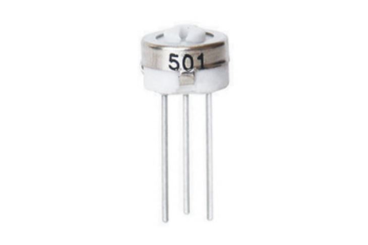
The 3362 Trimming Potentiometer is a single - turn trimmer potentiometer. It offers a compact and reliable solution for making fine adjustments to electrical circuits. With its high - quality construction, it provides stable resistance values over a wide range of operating conditions.
The key features of the 3362 Trimming Potentiometer include:

- Precision: It can provide precise resistance adjustments, which is essential for accurate gain control in a variable gain amplifier.
- Compact Size: Its small form factor makes it suitable for use in space - constrained applications, allowing for more flexible circuit board layouts.
- Good Temperature Stability: The potentiometer maintains its performance even when exposed to varying temperatures, ensuring consistent amplifier performance.
- Wide Resistance Range: It comes in a variety of resistance values, giving designers the flexibility to choose the most appropriate one for their specific amplifier requirements.
Basics of a Variable Gain Amplifier
Before delving into how to use the 3362 Trimming Potentiometer in a VGA, let's briefly review the basic principles of a variable gain amplifier. A VGA is designed to amplify an input signal, and the gain of the amplifier can be adjusted according to different needs. The gain of an amplifier is defined as the ratio of the output signal magnitude to the input signal magnitude.
In a typical amplifier circuit, the gain is determined by the values of the resistors and other components in the circuit. By changing the resistance values, we can change the gain of the amplifier. This is where the trimming potentiometer comes in handy.
Using the 3362 Trimming Potentiometer in a Variable Gain Amplifier
Circuit Design Considerations
When incorporating the 3362 Trimming Potentiometer into a variable gain amplifier circuit, there are several important design considerations:
- Location in the Circuit: The potentiometer should be placed in a position where it can effectively control the gain. In most cases, it is connected in the feedback path of the amplifier. For example, in an inverting amplifier circuit, the potentiometer can be used to adjust the feedback resistance, which directly affects the gain of the amplifier.
- Matching Resistance: The resistance value of the potentiometer should be carefully selected to match the other components in the circuit. If the resistance is too high or too low, it can lead to improper gain adjustment or even instability in the amplifier.
- Loading Effects: The potentiometer can introduce loading effects on the amplifier circuit. These effects can change the input and output impedance of the amplifier, which may affect its performance. Therefore, it is necessary to analyze and minimize these loading effects during the circuit design process.
Step - by - Step Installation
- Schematic Design: First, design the schematic of the variable gain amplifier circuit. Determine the appropriate position for the 3362 Trimming Potentiometer based on the circuit requirements. Draw the circuit diagram clearly, indicating all the components and their connections.
- Component Selection: Select all the necessary components for the amplifier circuit, including the 3362 Trimming Potentiometer, operational amplifiers, resistors, and capacitors. Make sure that all the components meet the specifications of the circuit design.
- PCB Layout: Design the printed circuit board (PCB) layout. Place the components on the PCB according to the schematic diagram, paying attention to the spacing and routing of the traces. Ensure that the potentiometer is easy to access for adjustment.
- Soldering: Solder all the components onto the PCB carefully. Use proper soldering techniques to ensure good electrical connections and mechanical stability.
- Testing and Calibration: After soldering, test the amplifier circuit. Apply an input signal to the amplifier and measure the output signal. Use a multimeter to adjust the 3362 Trimming Potentiometer until the desired gain is achieved.
Comparison with Other Trimming Potentiometers
There are other types of trimming potentiometers available in the market, such as the 3329 Trimming Potentiometer and the 3386 Trimming Potentiometer. While these potentiometers share some similarities with the 3362, there are also some differences.
The 3329 Trimming Potentiometer is also a single - turn trimmer, but it may have different resistance ranges and precision levels compared to the 3362. The 3386 Trimming Potentiometer might offer different physical sizes and temperature stability characteristics. When choosing a potentiometer for a variable gain amplifier, it is important to consider these differences and select the one that best suits the specific requirements of the circuit.
Troubleshooting and Tips
During the process of using the 3362 Trimming Potentiometer in a variable gain amplifier, you may encounter some problems. Here are some common issues and solutions:
- Inaccurate Gain Adjustment: If the gain adjustment is not accurate, it could be due to incorrect resistance selection or a faulty potentiometer. Check the resistance value of the potentiometer and make sure it is within the specified range. If the potentiometer is damaged, replace it with a new one.
- Noise in the Output Signal: Noise in the output signal can be caused by poor soldering, electromagnetic interference, or improper grounding. Check the soldering joints to ensure they are clean and solid. Use proper shielding techniques to reduce electromagnetic interference, and ensure that the circuit is properly grounded.
- Temperature - related Issues: If the amplifier performance changes with temperature, it may be due to the temperature coefficient of the potentiometer. Consider using a potentiometer with better temperature stability or adding temperature compensation circuits to the amplifier.
Conclusion
The 3362 Trimming Potentiometer is a valuable component for achieving variable gain in an amplifier. Its precision, compact size, and good temperature stability make it an ideal choice for a wide range of applications. By following the design considerations and installation steps outlined in this blog post, you can effectively use the 3362 Trimming Potentiometer in your variable gain amplifier circuits.
If you are interested in purchasing 3362 Trimming Potentiometers or have any questions about their applications, feel free to contact us for more information and to start a procurement negotiation. We are committed to providing high - quality products and excellent service to meet your needs.
References
- "Electronic Circuit Design Handbook", McGraw - Hill Education.
- "Operational Amplifiers and Linear Integrated Circuits" by Robert F. Coughlin and Frederick F. Driscoll.


