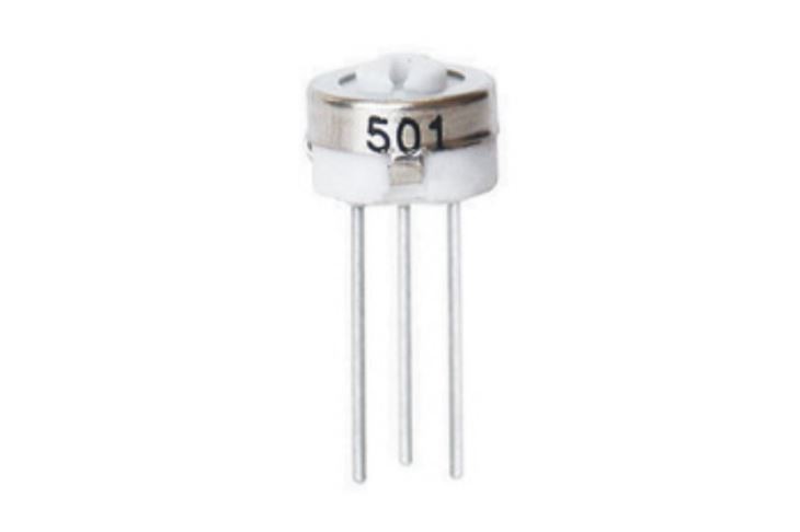
A trimming potentiometer, also known as a trim pot, is a type of variable resistor that is commonly used to fine - tune electrical circuits. Among various models, the 3329 Trimming Potentiometer is a popular choice due to its precision and reliability. As a supplier of the 3329 Trimming Potentiometer, I will guide you on how to use it in a voltage - dividing circuit.
Understanding the Basics of a Voltage - Dividing Circuit
Before delving into the use of the 3329 Trimming Potentiometer, let's first understand the concept of a voltage - dividing circuit. A voltage divider is a simple circuit that can reduce a large voltage into a smaller one. It consists of two or more resistors connected in series across a voltage source. The output voltage is taken from the connection point between the resistors.
The formula for calculating the output voltage ($V_{out}$) of a two - resistor voltage divider is given by:
$V_{out}=V_{in}\times\frac{R_2}{R_1 + R_2}$
where $V_{in}$ is the input voltage, $R_1$ and $R_2$ are the resistances of the two resistors.
Features of the 3329 Trimming Potentiometer
The 3329 Trimming Potentiometer has several features that make it suitable for voltage - dividing circuits. It is a single - turn potentiometer, which means it can be adjusted through a rotation of up to 360 degrees. This allows for relatively quick and easy adjustments.
It comes with a certain resistance range, which can be selected according to the requirements of the circuit. The precision of the 3329 Trimming Potentiometer ensures that the voltage division can be accurately controlled, making it ideal for applications where precise voltage levels are needed, such as in sensor calibration circuits or in the adjustment of bias voltages in amplifiers.
Using the 3329 Trimming Potentiometer in a Voltage - Dividing Circuit
Circuit Setup
To use the 3329 Trimming Potentiometer in a voltage - dividing circuit, you first need to set up the circuit. Connect the input voltage source ($V_{in}$) across the two outer terminals of the potentiometer. One terminal is connected to the positive side of the voltage source, and the other is connected to the negative side (usually ground).
The output voltage ($V_{out}$) is taken from the middle terminal of the potentiometer and one of the outer terminals. The middle terminal is the adjustable terminal, and by rotating the potentiometer, the resistance between the middle terminal and the outer terminals changes, thereby changing the output voltage.

Calculating the Output Voltage
The resistance of the potentiometer can be adjusted within its specified range. Let's assume the total resistance of the 3329 Trimming Potentiometer is $R_{total}$, and the resistance between the middle terminal and one of the outer terminals is $R$. If we connect the input voltage across the entire potentiometer and take the output voltage from the middle terminal and one of the outer terminals, the output voltage formula becomes:
$V_{out}=V_{in}\times\frac{R}{R_{total}}$
For example, if the input voltage $V_{in} = 10V$ and the total resistance of the potentiometer $R_{total}=10k\Omega$, and we adjust the potentiometer such that the resistance $R = 2k\Omega$, then the output voltage $V_{out}=10V\times\frac{2k\Omega}{10k\Omega}=2V$
Adjustment Process
When adjusting the 3329 Trimming Potentiometer, you can use a small screwdriver to turn the adjustment screw. As you turn the screw, the resistance changes, and you can monitor the output voltage using a voltmeter. Make small adjustments and observe the changes in the output voltage until you reach the desired voltage level.
Comparison with Other Trimming Potentiometers
While the 3329 Trimming Potentiometer is a great choice for many applications, there are other models available as well, such as the 3386 Trimming Potentiometer and the 3362 Trimming Potentiometer.
The 3386 Trimming Potentiometer may have a different resistance range and physical size compared to the 3329. It might be more suitable for applications where a larger resistance adjustment range is required.
The 3362 Trimming Potentiometer also has its own characteristics. It could offer better temperature stability or higher power - handling capabilities in some cases. The choice between these potentiometers depends on the specific requirements of your voltage - dividing circuit, such as the required resistance range, precision, and environmental conditions.
Applications of the 3329 Trimming Potentiometer in Voltage - Dividing Circuits
Sensor Calibration
In sensor calibration circuits, precise voltage levels are often needed to ensure accurate sensor readings. The 3329 Trimming Potentiometer can be used to adjust the reference voltage for the sensor. By fine - tuning the output voltage of the voltage - dividing circuit, the sensor can be calibrated to work within its optimal range.
Amplifier Bias Adjustment
In amplifier circuits, bias voltages need to be carefully adjusted to ensure proper operation. The 3329 Trimming Potentiometer can be used in a voltage - dividing circuit to provide the correct bias voltage to the amplifier's input stage. This helps to set the operating point of the amplifier and improve its performance.
Considerations When Using the 3329 Trimming Potentiometer
- Power Rating: Make sure that the power dissipated by the potentiometer does not exceed its power rating. The power dissipated in a resistor (or potentiometer) is given by $P = V\times I=I^{2}R=\frac{V^{2}}{R}$. Exceeding the power rating can lead to overheating and damage to the potentiometer.
- Environmental Conditions: The performance of the 3329 Trimming Potentiometer can be affected by environmental factors such as temperature and humidity. In harsh environments, additional protection or compensation measures may be required.
- Mechanical Stability: Ensure that the potentiometer is securely mounted to prevent accidental adjustments. Loose mounting can lead to fluctuations in the output voltage.
Conclusion
The 3329 Trimming Potentiometer is a valuable component for voltage - dividing circuits. Its precision and ease of adjustment make it suitable for a wide range of applications, from sensor calibration to amplifier bias adjustment. By understanding its features, how to set up the circuit, and the adjustment process, you can effectively use it to achieve the desired voltage levels in your circuits.
If you are interested in purchasing the 3329 Trimming Potentiometer or have any questions about its application in your voltage - dividing circuits, feel free to contact us for further discussion and procurement negotiations. We are committed to providing high - quality products and excellent technical support to meet your needs.
References
- Electronics textbooks on basic circuit theory.
- Manufacturer's datasheet for the 3329 Trimming Potentiometer.
- Technical articles on the use of trimming potentiometers in various applications.


