As a supplier of the 3329 Trimming Potentiometer, I've received numerous inquiries about how to test this crucial electronic component. Testing a 3329 Trimming Potentiometer is a fundamental skill for electronics enthusiasts, technicians, and engineers. In this blog post, I'll walk you through the step - by - step process of testing a 3329 Trimming Potentiometer, ensuring you can accurately evaluate its performance.

Understanding the 3329 Trimming Potentiometer
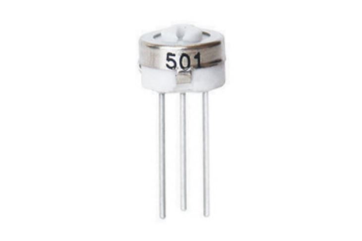
Before diving into the testing process, it's essential to understand what a 3329 Trimming Potentiometer is. A potentiometer is a three - terminal resistor with a sliding or rotating contact that forms an adjustable voltage divider. The 3329 Trimming Potentiometer is a single - turn device, which is commonly used for fine - tuning circuits, such as adjusting the gain of an amplifier or setting the bias of a transistor.
The 3329 Trimming Potentiometer typically has three pins: two outer pins and a center pin. The outer pins are connected to the ends of the resistive element, while the center pin is connected to the wiper. By adjusting the position of the wiper, the resistance between the center pin and one of the outer pins can be varied.
Tools Required for Testing
To test a 3329 Trimming Potentiometer, you'll need the following tools:
- Multimeter: A digital multimeter is the most commonly used tool for testing potentiometers. It can measure resistance, voltage, and current. Make sure your multimeter has a resistance measurement function.
- Screwdriver: Since the 3329 Trimming Potentiometer is adjusted using a screwdriver, you'll need a small, flat - head screwdriver that fits the adjustment slot of the potentiometer.
Step - by - Step Testing Process
Step 1: Safety First
Before starting the testing process, ensure that the circuit in which the potentiometer is installed is powered off. This will prevent any electrical shock and damage to the multimeter or the potentiometer.
Step 2: Visual Inspection
Examine the 3329 Trimming Potentiometer visually. Look for any signs of physical damage, such as cracks, burns, or loose connections. If you notice any damage, the potentiometer may be faulty and should be replaced.
Step 3: Set the Multimeter
Turn on the multimeter and set it to the resistance measurement mode. Select an appropriate range based on the expected resistance value of the potentiometer. For example, if the potentiometer has a nominal resistance of 10 kΩ, set the multimeter to the 20 kΩ range.
Step 4: Connect the Multimeter
Connect the probes of the multimeter to the outer pins of the 3329 Trimming Potentiometer. It doesn't matter which probe is connected to which outer pin. The multimeter should display the total resistance of the potentiometer. Compare this value with the nominal resistance value marked on the potentiometer. If the measured resistance is significantly different from the nominal value, the potentiometer may be faulty.
Step 5: Check the Wiper Resistance
Next, connect one probe of the multimeter to the center pin (wiper) and the other probe to one of the outer pins. Slowly turn the adjustment screw of the potentiometer using the screwdriver. As you turn the screw, the resistance value displayed on the multimeter should change smoothly. If the resistance value jumps or doesn't change at all, the potentiometer may be faulty.
Step 6: Test the Full Range
Repeat Step 5, but this time connect the probe to the other outer pin. Turn the adjustment screw from one end to the other, and make sure the resistance value changes continuously from close to zero to the total resistance of the potentiometer. This test ensures that the wiper moves smoothly across the entire resistive element.
Common Issues and Troubleshooting
During the testing process, you may encounter some common issues. Here are some possible causes and solutions:
1. Inconsistent Resistance Reading
- Cause: Dirt or debris on the resistive element or the wiper.
- Solution: Clean the potentiometer using a contact cleaner. Apply the cleaner to the adjustment slot and work the wiper back and forth a few times to remove any dirt.
2. Resistance Does Not Change
- Cause: A broken resistive element or a loose connection.
- Solution: Check the connections of the potentiometer. If the connections are okay, the potentiometer may need to be replaced.
3. Excessive Noise
- Cause: Poor contact between the wiper and the resistive element.
- Solution: Try cleaning the potentiometer. If the noise persists, the potentiometer may be worn out and should be replaced.
Comparison with Other Trimming Potentiometers
While the 3329 Trimming Potentiometer is a popular choice, there are other trimming potentiometers available in the market, such as the 3362 Trimming Potentiometer and the 3386 Trimming Potentiometer. Each of these potentiometers has its own characteristics and applications.
The 3362 Trimming Potentiometer offers higher precision and stability compared to the 3329, making it suitable for applications where accurate resistance adjustment is required. The 3386 Trimming Potentiometer, on the other hand, has a larger size and can handle higher power, making it ideal for high - power applications.
Conclusion
Testing a 3329 Trimming Potentiometer is a straightforward process that can be done using a multimeter and a screwdriver. By following the steps outlined in this blog post, you can quickly and accurately evaluate the performance of the potentiometer. If you encounter any issues during the testing process, refer to the troubleshooting section for possible solutions.
As a supplier of the 3329 Trimming Potentiometer, we are committed to providing high - quality products and excellent customer service. If you have any questions about our products or need assistance with testing or using the 3329 Trimming Potentiometer, please feel free to contact us for procurement and further discussions.
References
- Electronics Fundamentals: Circuits, Devices, and Applications, by Thomas L. Floyd
- The Art of Electronics, by Paul Horowitz and Winfield Hill


